commodore 128, 128D, 128DCR A/V Breakout For Sale

When you click on links to various merchants on this site and make a purchase, this can result in this site earning a commission. Affiliate programs and affiliations include, but are not limited to, the eBay Partner Network.

commodore 128, 128D, 128DCR A/V Breakout:
$19.99
Great device designed by commodore4ever.
Composite out. Mono or Stereo out (If your 128 has been modded with). Audio In.. SVideo out!
This device makes hooking up your 128 to a modern tv quick and simple.
Documentation for the 64 version as the 128 version functions the same.
The A/V-Adaptor allows to connect standard S-Video and Audio or Composite-Video cables to the A/V-Jack of the Commodore C64.
A 330 resistor to attenuate the Chroma signal for S-Video is installed, but it can be deactivated by setting a jumper (JP2). This attenuation is required, since the chroma signal has a level, which is too high for standard S-Video.
Further, the audio input can be connected to GND, in case it is not in use to reduce the noise introduction. The two audio output jacks can be connected by a jumper. Alternatively, the stereo sound output (A/V-Jack, pin 7, in case a 2nd SID is installed inside the C64) can be connected to the right channel of the audio output. The first SID output is connected to the left channel of the audio Signal
1 Luminance
2 GND
3 Audio Out (mono/left)
4 Composite Video
5 Audio In
6 Chrominance
7 Audio Out (right – if provided)
8 -S-Video Jack
A vertical PCB mount Mini-DIN jack (4 circuits)
Pin Signal
1 GND (Luminance)
2 GND (Chrominance)
3 Luminance
4 ChrominanceRCA-Jacks
Audio Out (mono/left)
Audio Out (mono/right)
Audio In
Composite chrominance signal has a too high level for the standard S-Video chroma signal. The jumper bridges the 330 resistor (R1) to switch off this attenuation.
Status Configuration
open Attenuation active
set Attenuation inactive/offAudio Input
To reduce the noise introduction to the Audio Input, this can be grounded.
Status Configuration
ON SID Audio In connected to
OFF SID Audio In connected to GND
Mono/Stereo
The standard audio output of the SID is one channel (mono). In cases a 2nd SID is installed, the 2nd audio output is (usually) connected to Pin 7 of the Audio/Video jack of the C64. JP3 connected the right channel of the audio output (J4) to either J2, Pin 3 or Pin 7.
Status Configuration
MONO J4 connected to J2, Pin 3
STEREO J4 connected to J2, Pin 7
check out a short video
Related Items:
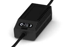
Commodore 128 Power Supply - C128 PSU, New Design, OLED display, Touch sensor
$79.99
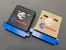
Commodore4ever Wifi Modem Commodore 64/128/Vic-20/Plus 4
$32.99
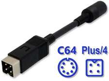
Commodore PSU Adapter C64 - C128 - Plus/4, Power Supply
$14.99
![]()
Documentation
- AIX Local Security Checks
- Backdoors
- CentOS Local Security Checks
- CGI abuses
- CISCO
- Databases
- Debian Local Security Checks
- Default Unix Accounts
- Denial of Service
- Fedora Local Security Checks
- Finger abuses
- Firewalls
- FreeBSD Local Security Checks