Commodore 16 116 64KB RAM Memory Addressing Module/Kit [C16 C116] Nonintrusive For Sale
![Commodore 16 116 64KB RAM Memory Addressing Module/Kit [C16 C116] Nonintrusive](img-large/g/aXgAAOSwxtxjL0Vy/s-l1600/Commodore-16-116-64KB-RAM-Memory-Addressing-Module.jpg "Commodore 16 116 64KB RAM Memory Addressing Module/Kit [C16 C116] Nonintrusive")
When you click on links to various merchants on this site and make a purchase, this can result in this site earning a commission. Affiliate programs and affiliations include, but are not limited to, the eBay Partner Network.

Commodore 16 116 64KB RAM Memory Addressing Module/Kit [C16 C116] Nonintrusive:
$3.95
Overview
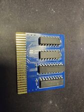
This listing is for one (1) 64KB addressing PCB-pair ineither a PCB-only, unassembled module, or fully assembled configuration. The replacement 64KB RAM modules areNOTincluded.
The module implements a modification for the Commodore 16 and Commodore 116 computers, allowing either to address 16KB or 64KB of RAM. The PCBs install between the 74LS257 ICs and do not require cutting traces or lifting pins (a common suggestion in other implementations of this modification). Please review the installation instructions below as this modification requires soldering and desoldering of components from an unmodified/factory-condition computer.
Demonstration and video overview of this adapter dir=\"ltr\" style=\"font-size: 14pt; margin-top: 0px; margin-bottom: 0px;\">
Please send me a message if you are interested in purchasing more than the listed quantity as I may be able to satisfy the request by using parts from another listing. Combined shipping is also available for multiple purchases. If purchasing more than unit, please request or wait for an invoice prior to submitting payment so to ensure that combined shipping is applied.
For assembled modules:
- Solder joints will be inspected for tidiness and cleaned of excessive flux.
- The board will be tested by ensuring proper continuity between male and female pins.
- The PCB pair requires separation through the existing slot (see photos).
- Wire and flush cutters are suitable for this task and the end result requires little to no sanding to remove excess material.
The following hardware is used in the unassembled and assembled configurations:
- 64KB Addressing PCB pair
- Four (4) 8-pin round male headers
- Tow (2) 16-pin DIP sockets
- Two (2) female/female Dupont cables, ~30cm in length (random color selection)
- One (1) 2-pin angled male header
- Two (2) 2-pin female jumpers
- Two (2) 1-pin angled male headers
- Two (2) 3-pin male headers
- Two (2) 2-pin jumpers
8-pin ROUND male headers are used in the PCB assembly to ensure compatibility with both sockets and a system-board-direct installation.
The photos also show an example of a fully assembled PCB, and an example of a fully assembled installation in a Commodore 16 computer. There is also a photo of the PCB in its factory condition,which must be cut through the center perforation along the existing gap before use (see above note for PCB-only orders).
PCB Dimensions: 28mm x 21mm
U7 PCB Overhead (relative to TOP): 7.0mm above pins 9-16 (*); 6.4mm below pins 1-8; 3.8mm above pins 1,16 (IC notch); 6.4mm below pins 8,9.
U8 PCB Overhead (relative to TOP): 6.4mm above pins 9-16; 7.0mm below pins 1-8 (*); 3.8mm above pins 1,16 (IC notch); 6.4mm below pins 8,9.
(*) Approximated due to filing of edge.
Installation Instructions
System Board Preparation(assumes factory Commodore 16 installation)
- Desolder and SAVE both 74LS257 IC modules, marked U7 and U8 on the system board.
- Desolder and REPLACE both TMS4416 DRAM IC modules, marked U5 and U6 on the system board. Replace these ICs with DRAM models 4464 or 41464, 150ns or faster (e.g. NEC D41464C-10).
- You may install the new DRAM in a socket or directly in the system board. NOTE: These modules are compatible with the removed memory and will continue to provide 16KB of RAM without any further modifications.
- Locate the two vias immediatelyadjacent to the RF modulator and between the cartridge port. Using a multimeter, verify continuity from pins 21 and 22 of the CPU and theidentified vias. Solder the 2-pin angled male header into identifiedvias (please see photos for an example).
- Alternatively, you may separate the header and install it into two vias below the REV text on the system board that are also connected to the aforementioned CPU pins. Please use a multimeter to verify continuity prior to any attempted installation.
PCB Installation
- The footprints labelled 8KB/32KB control the addressing mode of the 74LS257. You may use the provided jumper or an external switch to select between modes; the center pin is the COMMON connection, and one of the two modes MUST always be selected for proper operation.
- The footprints labelled \"U2 21\" and \"U2 22\" designate the connection point to the previously installed 2-pin angled male header, which connects to pins 21 and 22 of the CPU. Use a suitable wire (or the provided Dupont cable for applicable configurations) to complete the connection between the PCB and installed 2-pin angled header (please see photos for an example).
- Ensure that each 74LS257 IC is inserted in the PCB with the proper orientation; note pin 1 on the silkscreen. Ensure that the PCB is inserted into the system board (or riser socket) using similar markings on the system board as a reference.
Each of the computers in the Commodore-264 series (16, Plus/4, 116) has different clearance between the system board and the bottom of the keyboard, so please evaluate your situation carefully prior to purchase. I have only verified this modification to install into a riser socket within a Commodore 16, with each 74LS257 IC installed in a socket on the PCB. In this configuration, the RF shield makes contact with the top of the 74LS257. That said, the PCB is designed for compactness and should install directly to the system board in both the Commodore 16 and 116 without the need for a riser socket; please verify with above dimensions prior to purchase.
Related Items:
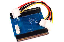
PC1-XT - ISA/XT adapter for the Commodore PC-1 retro computer
$39.00
![Commodore/MOS 6510/8500 to 7501/8501 CPU Adapter PCB/Module [C16 Plus/4 C116] picture](/store/img/g/OmYAAOSwgH1kYANL/s-l225/Commodore-MOS-6510-8500-to-7501-8501-CPU-Adapter-P.jpg)
Commodore/MOS 6510/8500 to 7501/8501 CPU Adapter PCB/Module [C16 Plus/4 C116]
$5.95
$15.00
![]()
Documentation
- AIX Local Security Checks
- Backdoors
- CentOS Local Security Checks
- CGI abuses
- CISCO
- Databases
- Debian Local Security Checks
- Default Unix Accounts
- Denial of Service
- Fedora Local Security Checks
- Finger abuses
- Firewalls
- FreeBSD Local Security Checks